
Control Installations
The service life and accuracy of a control system can be influenced by installation factors. This tutorial discusses the basic important considerations including the positioning of equipment and wiring, radio frequency interference, and protection from the environment.
Temperature sensors
Temperature sensors
Sensor location
The position of the sensor is important, and it must be located where it can sense a representative pressure, temperature or level.
The length of the sensor must also be considered. If the sensor to be used is large or long, provision has to be made for this in the pipework into which it is installed.
Sensors for self-acting control systems can come in many different shapes and sizes. Generally,the sensors for electronic and pneumatic control systems are smaller than those for self-acting controls.
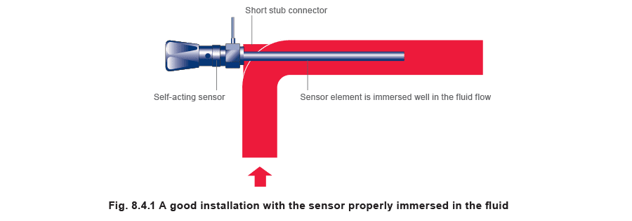
The next requirement is to position the sensor in a location where it is not susceptible to damage,and perhaps to fit it in a pocket if necessary.
The pocket must be long enough to enable the whole sensor to be immersed in the liquid. If, in Figure 8.4.1, the stub connector were longer, the sensor might not be properly immersed in the fluid.
 Sensor protection
If the sensor is to be installed in a tank, it may be better to locate it close to one of the corners, where the greatest wall strength might be expected, with less chance of flexing.
With some fluids it is necessary to protect the sensor to prevent it from being corroded or dissolved.
Pockets are usually available in various materials, including:
Sensor protection
If the sensor is to be installed in a tank, it may be better to locate it close to one of the corners, where the greatest wall strength might be expected, with less chance of flexing.
With some fluids it is necessary to protect the sensor to prevent it from being corroded or dissolved.
Pockets are usually available in various materials, including:
- Stainless steel.
- Mild steel.
- Copper and brass, which are suitable for the less severe applications.
- Heat resistant glass, which offers good general protection against corrosive products like acids and alkalis, but these can be fragile. Self-acting control capillary tubes can usually be supplied covered with a PVC coating, which is useful in corrosive environments. Where it is possible to fit the sensor through the side of the tank, the provision of a pocket also allows the sensor to be removed without draining the contents. A pocket will tend to increase the time lag before the control can respond to changes in solution temperature, and it is important to make arrangements to keep this to a minimum. There will, for instance, be an air space between the sensor and the inside of the pocket, and air is an insulator. To overcome this, a heat conducting paste can be used to fill the space.
Valves and actuators
Valves and actuators
The preferred actuator position will depend upon the type of control system used. For self-acting control valves, it is generally preferable if the actuator is fitted underneath the valve. Conversely, it is usually better to fit an electrical or pneumatic actuator above the valve, otherwise any leakage from the stem may result in process fluid, which may be hot or corrosive, spilling onto the actuator. Horizontal fitting is not recommended as over a period of time:
- Uneven stem wear may occur.
- The valve plug may not present itself squarely to the valve seat. The material construction of electric actuators must be appropriate to the environment in terms of the enclosure rating against excess moisture, and hazardous gases and liquids. The valve and actuator will be heavier than an equivalent length of pipe, and will need adequate support. It is important, before and after installation, to check that the valve is installed with its flow arrow in the correct direction. Enough space must be left around the valve and actuator for maintenance, and to lift the actuator off the valve.
Radio frequency interference (RFI)
Radio frequency interference (RFI)
Radio frequency interference is electrical noise that can cause corruption of control signals and affect the operation of electronic controllers. There are two forms of RFI:
- Continuous
- Impulse (transient). Radio transmitters, computers, induction heaters, and other such equipment emit continuous high frequency radio interference. Impulse interference is generated from electrical arcing, which can occur on the opening of switch contacts especially those responsible for switching inductive components, such as motors or transformers. The control engineer is often most concerned about impulse interference. The pulses are of very high intensity and very short duration, and can disturb genuine electrical control signals. Transmission of RFI Radio interference can travel via two modes:
- Conduction.
- Radiation. Conducted interference is communicated to the controller via mains supply cables. Having an interference suppressor in the supply as close to the controller as possible can reduce its effect. Radiated interference is a greater problem because it is harder to counteract. This form of interference is like a broadcast transmission being picked up by ‘aerials’ naturally formed by the signal wiring, and then re-emitted within the controller box to more sensitive areas. The electronic components within the controller can also receive transmissions directly, especially if the interference source is within 200 mm. Effects of RFI Controller types respond to different forms of interference in different ways. Analogue controllers will usually respond to continuous rather than transient interference but will usually recover when the interference ceases. The symptoms of continuous interference are not easily recognisable because they usually influence the measurement accuracy. It is often difficult to distinguish between the effects of interference and the normal operation of the device. Transient interference is more likely to affect relay outputs, as its occurrence is faster than that which the analogue circuits can respond. Microprocessor based controllers are more subject to corruption from transient impulse interference but have a higher immunity to continuous interference. The first indication that interference has occurred is often that the display has locked up, is scrambled or contains meaningless symbols in addition to the normal display. More difficult symptoms to detect include measurement inaccuracies or incorrect actuator position, this may continue undetected until the system is clearly out of control. Installation practice to limit RFI The correct selection and installation of control signal wiring is vital to reduce susceptibility to RFI. Twisted pairs of wires are less susceptible to interference than parallel run cables (Figure 8.4.2). Earthed screened cables are even less susceptible to interference than twisted pairs of wires, but this cannot always be relied on, especially near high current cables.
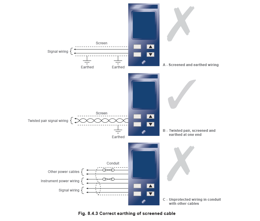
 Screened cable (Figures 8.4.3) should only be earthed at one end, see Figure 8.4.3 (‘A’ and ‘B’); earthing at both ends will lead to a deterioration in this situation.
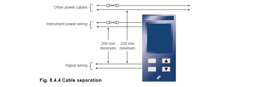
 Keeping wires separate from power wiring (Figure 8.4.4) can reduce pick-up via the signal wires.
BS 6739: 1986 recommends that this separation should be at least 200 mm for instrument power wiring and 250 mm for other power cables.
Keeping wires separate from power wiring (Figure 8.4.4) can reduce pick-up via the signal wires.
BS 6739: 1986 recommends that this separation should be at least 200 mm for instrument power wiring and 250 mm for other power cables.
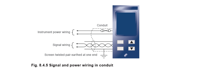
 It has been found in practice that signal wires can be run alongside / close to power wiring providing they are contained within their own earthed screen, see Figure 8.4.5.
 Impulse interference generated from electrical arcing can be reduced by means of an appropriate suppressor connected across switch contacts.
Pick-up via direct radiation can be reduced by installing the controllers at least 250 mm away from interference sources, such as contact breakers or mains switching relays.
Cable separation
The following information is reprinted from the British Standard Code of Practice for Instrumentation
in Process Control systems: installation design and practice BS 6739: 1986:
Paragraph 10.7.4.2.2 - Separation from power cables
Impulse interference generated from electrical arcing can be reduced by means of an appropriate suppressor connected across switch contacts.
Pick-up via direct radiation can be reduced by installing the controllers at least 250 mm away from interference sources, such as contact breakers or mains switching relays.
Cable separation
The following information is reprinted from the British Standard Code of Practice for Instrumentation
in Process Control systems: installation design and practice BS 6739: 1986:
Paragraph 10.7.4.2.2 - Separation from power cables
- Instrument cables should be routed above or below ground, separated from electrical power cables (i.e. ac, cables usually above 50 Vac with a 10 A rating).
- Parallel runs of cables should be avoided. However, where this is unavoidable, adequate physical separation should be provided.
- A spacing of 250 mm is recommended from ac power cables up to 10 A rating. For higher ratings, spacing should be increased progressively.
- Where it is unavoidable for signal and power cables to cross over each other, the cables should be arranged to cross at right angles with a positive means of separation of at least 250 mm. Paragraph 10.7.4.2.3 - Separation between instrument cables
- Categories 1 and 2 spaced 200 mm.
- Categories 2 and 3 spaced 300 mm.
- Categories 1 and 3 spaced 300 mm. Cables are categorised as follows:
- Power cables ac- Cables usually above 50 Vac with a 10 amp rating.
- Category 1. Instrument power and control wiring above 50 V - This group includes ac and dc power supplies and control signals up to 10 A rating.
- Category 2. High-level signal wiring (5 V to 50 Vdc) - This group includes digital signals, alarm signals, shutdown signals and high level analogue signals e.g. 4 - 20 mA.
- Category 3. Low-level signal wiring (below 5 Vdc) - This group includes temperature signals and low-level analogue signals. Thermocouple wiring comes within this category. Although it is not always practical, every effort should be made to achieve the recommended separations given.
Electrical protection standards
Electrical protection standards
Electrical equipment such as electronic controllers must be suitable for the environment in which they are to be used. Hazardous environments may be found in oil refineries, offshore platforms, hospitals, chemical plants, mines, pharmaceutical plants and many others. The degree of protection will alter depending on the potential hazard, for example the risk of sparks or hot surfaces igniting flammable gases and vapours which may be present.
It is equally important to safeguard equipment against moisture, dust, water ingress, and severe changes in temperature.
Standards and procedures exist to reduce the chance of equipment inducing faults, which might otherwise start fires or initiate explosions in adjacent equipment.
Basic standards of protection have been devised to cater for specific environments.
IP ratings
The IP, or international protection rating stated for an enclosure, is a means of grading the protection level offered by the enclosure, by using two figures, as shown in Tables 8.4.1 and 8.4.2.
The first figure (see Table 8.4.1) refers to the protection offered against the intrusion of foreign objects such as levers, screwdrivers or even a person's hand. The range consists of seven digits commencing with 0, designating no protection offered from material objects or human intervention; up to 6, offering meticulous protection against the entry of dust or extremely fine particles.
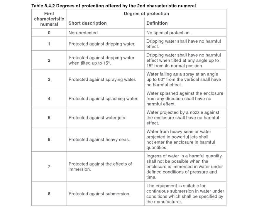
 The second figure (see Table 8.4.2) indicates the degree of protection against water intrusion.
The range commences with 0 meaning no protection against water. The highest is 8, giving optimum protection for equipment being continuously immersed in water.
The second figure (see Table 8.4.2) indicates the degree of protection against water intrusion.
The range commences with 0 meaning no protection against water. The highest is 8, giving optimum protection for equipment being continuously immersed in water.
 Example 8.4.1
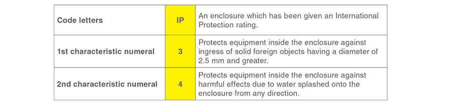
An electrical enclosure having the following IP34 rating can be defined as follows:
Example 8.4.1
An electrical enclosure having the following IP34 rating can be defined as follows:
 It is not the intention of this Module to enter into detail regarding the subject of enclosure protection.
The subject is discussed in much further depth in International Standards, BS EN 60529:1992 being one of them. The reader is advised to refer to such standards if information is required for specific purposes.
Explosion protected electrical equipment
It has been shown briefly how IP ratings cover two important areas of protection. There are, however, numerous other types of hazard to contend with. These may include corrosion, vibration, fire and explosion. The latter are likely to occur when electrical equipment produce sparks, operate at high temperatures, or arc; thus igniting chemicals, oils or gases.
In practice, it is difficult to determine whether or not an explosive atmosphere will be present at a specific place within a potentially hazardous area or plant. This problem has been resolved by assigning an area within the plant where flammable gases may be present to one of the following three hazardous zones:
It is not the intention of this Module to enter into detail regarding the subject of enclosure protection.
The subject is discussed in much further depth in International Standards, BS EN 60529:1992 being one of them. The reader is advised to refer to such standards if information is required for specific purposes.
Explosion protected electrical equipment
It has been shown briefly how IP ratings cover two important areas of protection. There are, however, numerous other types of hazard to contend with. These may include corrosion, vibration, fire and explosion. The latter are likely to occur when electrical equipment produce sparks, operate at high temperatures, or arc; thus igniting chemicals, oils or gases.
In practice, it is difficult to determine whether or not an explosive atmosphere will be present at a specific place within a potentially hazardous area or plant. This problem has been resolved by assigning an area within the plant where flammable gases may be present to one of the following three hazardous zones:
- Zone 1 - An area where the explosive gas is continuously present or is present for long periods of time.
- Zone 2 - An area where the explosive gas is likely to occur during normal operation.
- Zone 3 - An area where the explosive gas is not likely to occur during normal operation and if it does, will exist only for a short period of time. There have been many attempts to formulate internationally accepted standards of protection. The IEC (International Electrotechnical Commission) were the first to produce international standards in this area, however, CENELEC (European, Electrical Standards Co-ordination Committee) currently unites all the major European manufacturing countries under one set of standards. Measurement and control equipment is covered by an intrinsic safety protection method, which is based upon the reduction of explosive risk by restricting the amount of electrical energy entering a hazardous area, and therefore does not, in principle, require special enclosures. There are two categories of intrinsically-safe apparatus defined by the CENELEC and IEC, namely,EX ia and EX ib. EX ia class This classifies equipment as not being able to cause ignition under normal operational procedures, or as a result of a single fault or any two entirely independent faults occurring. EX ib class This classifies equipment as not being able to cause ignition under normal operational procedures, or as a result of a single fault occurring. As with IP protection, this Module does not intend to discuss this subject in any great depth; it is a complex subject further complicated by the fact that groupings of equipment can be different in different countries. It is suggested that, if the reader requires further information on this subject matter, he or she studies the appropriate relevant standard.