
Air Venting, Heat Losses and a Summary of Various Pipe Related Standards
The venting of air and other incondensable gases from steam systems, and the provision of adequate insulation, are vital to ensure steam plant efficiency, safety and performance.
Air venting
Air venting
When steam is first admitted to a pipe after a period of shutdown, the pipe is full of air. Further amounts of air and other non-condensable gases will enter with the steam, although the proportions of these gases are normally very small compared with the steam. When the steam condenses, these gases will accumulate in pipes and heat exchangers. Precautions should be taken to discharge them. The consequence of not removing air is a lengthy warming up period, and a reduction in plant efficiency and process performance. Air in a steam system will also affect the system temperature. Air will exert its own pressure within the system, and will be added to the pressure of the steam to give a total pressure. Therefore, the actual steam pressure and temperature of the steam/air mixture will be lower than that suggested by a pressure gauge. Of more importance is the effect air has upon heat transfer. A layer of air only 1 mm thick can offer the same resistance to heat as a layer of water 25 μm thick, a layer of iron 2 mm thick or a layer of copper 15 mm thick. It is very important therefore to remove air from any steam system. Automatic air vents for steam systems (which operate on the same principle as thermostatic steam traps) should be fitted above the condensate level so that only air or steam/air mixtures can reach them. The best location for them is at the end of the steam mains as shown in Figure 10.5.1. The discharge from an air vent must be piped to a safe place. In practice, a condensate line falling towards a vented receiver can accept the discharge from an air vent.
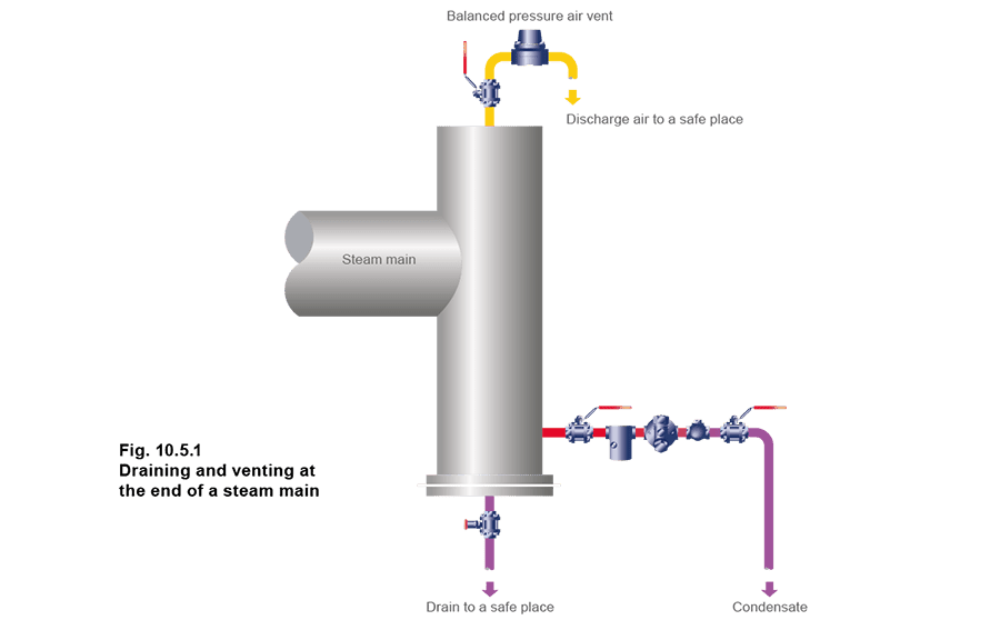
The discharge from an air vent must be piped to a safe place. In practice, a condensate line falling towards a vented receiver can accept the discharge from an air vent.
In addition to air venting at the end of a main, air vents should also be fitted:
- In parallel with an inverted bucket trap or, in some instances, a thermodynamic trap. These traps are sometimes slow to vent air on start-up.
- In awkward steam spaces (such as at the opposite side to where steam enters a jacketed pan).
- Where there is a large steam space (such as an autoclave), and a steam/air mixture could affect the process quality.
Reduction of heat losses
Reduction of heat losses
Even when a steam main has warmed up, steam will continue condensing as heat is lost by radiation. The condensing rate will depend upon the steam temperature, the ambient temperature, and the efficiency of the pipe insulation. For a steam distribution system to be efficient, appropriate steps should be taken to ensure that heat losses are reduced to the economic minimum. The most economical thickness of insulation will depend upon several factors:
- Installation cost.
- The heat carried by the steam.
- Size of the pipework.
- Pipework temperature. When insulating external pipework, dampness and wind speed must be taken into account. The effectiveness of most insulation materials depends on minute air cells which are held in a matrix of inert material such as mineral wool, fibreglass or calcium silicate. Typical installations use aluminium clad fibreglass, aluminium clad mineral wool and calcium silicate. It is important that insulating material is not crushed or allowed to waterlog. Adequate mechanical protection and waterproofing are essential, especially in outdoor locations. The heat loss from a steam pipe to water, or to wet insulation, can be as much as 50 times greater than from the same pipe to air. Particular care should be taken to protect steam lines, running through waterlogged ground, or in ducts, which may be subjected to flooding. The same applies to protecting the lagging from damage by ladders etc., to avoid the ingress of rainwater. It is important to insulate all hot parts of the system with the exception of safety valves. This includes all flanged joints on the mains, and also the valves and other fittings. It was, at one time, common to cut back the insulation at each side of a flanged joint, to leave access to the bolts for maintenance purposes. This is equivalent to leaving about 0.5 m of bare pipe. Fortunately, prefabricated insulating covers for flanged joints and valves are now more widely available. These are usually provided with fasteners so that they can readily be detached to provide access for maintenance purposes.
Calculation of heat transfer
Calculation of heat transfer
The calculation of heat losses from pipes can be very complex and time consuming, and assume that obscure data concerning pipe wall thickness, heat transfer coefficients and various derived constants are easily available, which, usually, they are not. The derivations of these formulae are outside the scope of this Module, but further information can be readily found in any good thermodynamics textbook. To add to this, an abundance of contemporary computer software is available for the discerning engineer. This being so, pipe heat losses can easily be found by reference to Table 10.5.1 and a simple equation (Equation 2.12.2). The table assumes ambient conditions of between 10 - 21°C, and considers heat losses from bare horizontal pipes of different sizes with steam contained at various pressures.
Table 10.5.1 Heat emission from pipes
Table 10.5.1 Heat emission from pipes
Note: Heat emission from bare horizontal pipes with ambient temperatures between 10°C and 20°C and still air conditions
| Temperature difference steam to air °C | Pipe size (DN) | |||||||||
| 15 | 20 | 25 | 32 | 40 | 50 | 65 | 80 | 100 | 150 | |
| W/m | ||||||||||
| 60 | 60 | 72 | 88 | 111 | 125 | 145 | 172 | 210 | 250 | 351 |
| 70 | 72 | 87 | 106 | 132 | 147 | 177 | 209 | 253 | 311 | 432 |
| 80 | 86 | 104 | 125 | 155 | 174 | 212 | 248 | 298 | 376 | 519 |
| 90 | 100 | 121 | 146 | 180 | 203 | 248 | 291 | 347 | 443 | 610 |
| 100 | 116 | 140 | 169 | 207 | 233 | 287 | 336 | 400 | 514 | 706 |
| 110 | 132 | 160 | 193 | 237 | 267 | 328 | 385 | 457 | 587 | 807 |
| 120 | 149 | 181 | 219 | 268 | 302 | 371 | 436 | 517 | 664 | 914 |
| 130 | 168 | 203 | 247 | 301 | 342 | 417 | 490 | 581 | 743 | 1 025 |
| 140 | 187 | 226 | 276 | 337 | 382 | 464 | 547 | 649 | 825 | 1 142 |
| 150 | 208 | 250 | 306 | 374 | 424 | 514 | 607 | 720 | 911 | 1 263 |
| 160 | 229 | 276 | 338 | 413 | 469 | 566 | 670 | 794 | 999 | 1 390 |
| 170 | 251 | 302 | 372 | 455 | 515 | 620 | 736 | 873 | 1 090 | 1 521 |
| 180 | 275 | 330 | 407 | 499 | 566 | 676 | 805 | 955 | 1 184 | 1 658 |
| 190 | 299 | 359 | 444 | 544 | 615 | 735 | 877 | 1041 | 1 281 | 1 800 |
| 200 | 325 | 389 | 483 | 592 | 681 | 795 | 951 | 1 130 | 1 381 | 1 947 |
Other factors can be included in the equation, for instance, if a pipe is lagged with insulation providing a reduction in heat losses to 10% of the uninsulated pipe, then it is multiplied by a factor of 0.1.
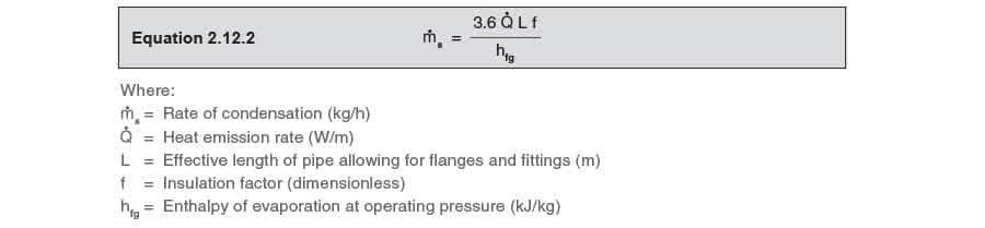
Note: The constant 3.6 gives the answer in kg/h Equivalent lengths:
- Pair of mating flanges 0.5 m
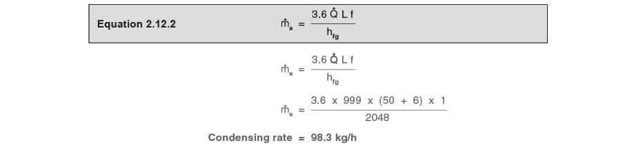
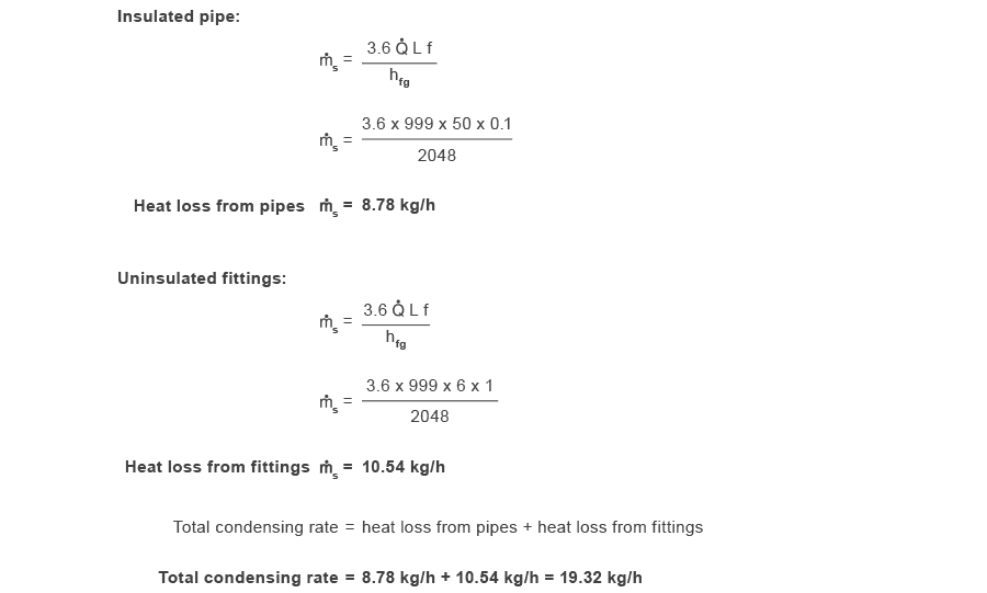
- Line size valve 1.0 m Example 10.5.1 50 m of 100 mm pipe has 8 pairs of flanges and two valves, and carries saturated steam at 7 bar g. Ambient temperature is 10°C, and the insulation efficiency is given as 0.1 With reference to Table 10.5.1 and the application of Equation 10.5.1: determine the quantity of steam that will be condensed per hour: Part 1 - Without insulation. Part 2 - With the pipe insulated, but the valves and flanges are left without insulation. Part 3 - Completely insulated. Equivalent length of fittings:
- (8 pairs of flanges @ 0.5 m) + (2 valves @ 1.0 m) = 6.0 m of pipe
- Saturated steam at 7 bar g:

Part 1 - Without insulation:
Part 2 - Pipe insulated, but without insulation on the valves and flanges: Consider the two elements separately:
Part 3 - Pipe and fittings insulated:

Relevant UK and International Standards
Relevant UK and International Standards
Symbols have been used to indicate, technically equivalent standards (=), and related standards (≠) respectively.
Table 10.5.2
Table 10.5.2
| BS 10 | Specification for flanges and bolting for pipes, valves and fittings. |
| BS 21 = ISO 7/1 ≠ ISO 7/2 | Specification for pipe threads for tubes and fittings where pressure tight joints are made on the threads. |
| EN 13480 | Specification for metallic industrial piping. |
| BS 1306 | Specification for copper and copper alloy piping systems. |
| EN 10255 | Specification for screwed and socketed tubes and tubulars and for plain end steel tubes suitable for welding and screwing to BS 21 pipe threads. |
| BS 1560 | Circular flanges for pipes, valves and fittings (Class designated): - Part 3, Section 3.1 - Specification for steel flanges (≠ ISO 7005). - Part 3, Section 3.2 - Specification for cast iron flanges (≠ ISO 7005-2). - Part 3, Section 3.3 - Specification for copper alloy and composite flanges (≠ ISO 7005-3). |
| BS 1600 | Dimensions of steel pipe for the petroleum industry. |
| EN 10253-1 | Specification for butt welding pipe fittings for pressure purposes. |
| BS 1710 | Specification for identification of pipelines. |
| BS 2779= IS0 228/1, ISO 228/2 | Specification for pipe threads for tubes and fittings where pressure tight joints are not made on the threads. |
| EN 10220 | Specification for dimensions and masses per unit length of welded and seamless steel pipes and tubes for pressure purposes. |
| BS 3601 | Specification for steel pipes and tubes with specified room temperature properties for pressure purposes. |
| EN 10216-2 EN 10217-2/3/5 | Specification for steel pipes and tubes for pressure purposes: carbon and carbon manganese steel with specified elevated temperature properties. |
| EN 10216-4 EN 10217-4 | Specification for carbon and alloy steel pipes and tubes with specified low temperature properties for pressure purposes. |
| EN 10216-2 EN 10217-2 BS 3604-2 | Steel pipes and tubes for pressure purposes: ferritic alloy steel with specified elevated temperature properties. |
| BS 3605-1/2 | Austenitic stainless steel pipes and tubes for pressure purposes. |
| BS 3799 | Specification for steel pipe fittings, screwed and socket welded for the petroleum industry. |
| BS 3974 | Specification for pipe supports. |
| EN 1092-1 | 3.1 - Specification for steel flanges; |
| EN 1092-2 | 3.2 - Specification for cast iron flanges (≠ ISO 7005-2); |
| BS 4504 | 3.3 - Specification for copper alloy and composite flanges (≠ ISO 7005-3). |
Summary
Summary
To summarise the ‘Steam Distribution’ Block of The Steam and Condensate Loop, the following checklist may be used to ensure that a steam distribution system will operate efficiently and effectively: