Bottom Blowdown
Factors surrounding the removal of suspended solids from the boiler, including valves, piping and blowdown vessels, with calculations.
Bottom Blowdown
Bottom Blowdown
Suspended solids can be kept in suspension as long as the boiler water is agitated, but as soon as the agitation stops, they will fall to the bottom of the boiler. If they are not removed, they will accumulate and, given time, will inhibit heat transfer from the boiler fire tubes, which will overheat and may even fail. The recommended method of removing this sludge is via short, sharp blasts using a relatively large valve at the bottom of the boiler. The objective is to allow the sludge time to redistribute itself so that more can be removed on the next blowdown. For this reason, a single four-second blowdown every eight hours is much more effective than one, twelve-second blowdown in the first eight hour shift period, and then nothing for the rest of the day. Blowdown water will either pass into a brick-lined blowdown pit encased below ground, or a metal blowdown vessel situated above ground. The size of the vessel is determined by the flowrate of blowdown water and flash steam that enters the vessel when the blowdown valve is opened. The major influences on blowdown rate are:
- The boiler pressure
- The size of the blowdown line.
- The length of the blowdown line between the boiler and the blowdown vessel.
In practice, a reasonable minimum length of blowdown line is 7.5 m, and most blowdown vessels are sized on this basis. Blowdown lines will contain bends, check valves and the blowdown valve itself; and these fittings will increase the pressure drop along the blowdown line. They may be thought of in terms of an 'equivalent straight length of pipe', and can be added to the pipe length to give an overall equivalent length. Table 3.14.1 gives equivalent lengths of various valves and fittings.
In practice, a reasonable minimum length of blowdown line is 7.5 m, and most blowdown vessels are sized on this basis. Blowdown lines will contain bends, check valves and the blowdown valve itself; and these fittings will increase the pressure drop along the blowdown line. They may be thought of in terms of an 'equivalent straight length of pipe', and can be added to the pipe length to give an overall equivalent length. Table 3.14.1 gives equivalent lengths of various valves and fittings.
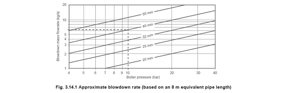
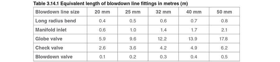 In the unlikely event that the total equivalent length is less than 7.5 m, the vessel should be sized on a higher flowrate. In these cases, multiply the boiler pressure by 1.15 to calculate the blowdown rate from Figure 3.14.1. Blowdown lines over 7.5 m can be read straight from this graph.
Example 3.14.1: For a boiler pressure of 10 bar g, an equivalent 40 mm blowdown line length is calculated to be 10 m, consequently, the blowdown rate is 6.2 kg/s (see Figure 3.14.1).
In the unlikely event that the total equivalent length is less than 7.5 m, the vessel should be sized on a higher flowrate. In these cases, multiply the boiler pressure by 1.15 to calculate the blowdown rate from Figure 3.14.1. Blowdown lines over 7.5 m can be read straight from this graph.
Example 3.14.1: For a boiler pressure of 10 bar g, an equivalent 40 mm blowdown line length is calculated to be 10 m, consequently, the blowdown rate is 6.2 kg/s (see Figure 3.14.1).
 There are two important factors to recognise with bottom blowdown:
Energy content of blowdown
The energy contained in the water being blown down is the liquid enthalpy of water at saturation temperature at boiler pressure. In Example 3.14.1, the boiler pressure is 10 bar g, and from steam tables, hf is 782 kJ/kg. So the rate at which energy is being released from the boiler is:
782 kJ/kg x 6.2 kg/s = 4.85 MW
Change in volume
Over a 3 second blowdown period, the amount of water blown down is:
6.2 kg/s x 3 seconds = 18.6 kg
The volume of the 18.6 kg of water blown down is:
18.6 kg x 0.001 m3/kg = 0.018 6 m3
From flash steam calculations, 16% of water at 10 bar g saturation temperature will flash to steam when the pressure is reduced to atmospheric. Steam at atmospheric pressure has a significantly greater volume than water and each kilogram occupies 1.673 m3 of space.
The resulting volume of flash steam from the 18.6 kg of boiler water is:
(18.6 kg x 16%) x 1.673 m3/kg = 4.98 m3
For comparison, the volume of water, is reduced to:
(18.6 kg x 84%) x 0.001 m3/kg = 0.015 6 m3
The very high energy flowrate, and huge change in volume between the upstream and downstream sides of the blowdown valve, mean that substantial reactionary forces are developed, and that boiler blowdown must be handled in a safe manner.
There are two important factors to recognise with bottom blowdown:
Energy content of blowdown
The energy contained in the water being blown down is the liquid enthalpy of water at saturation temperature at boiler pressure. In Example 3.14.1, the boiler pressure is 10 bar g, and from steam tables, hf is 782 kJ/kg. So the rate at which energy is being released from the boiler is:
782 kJ/kg x 6.2 kg/s = 4.85 MW
Change in volume
Over a 3 second blowdown period, the amount of water blown down is:
6.2 kg/s x 3 seconds = 18.6 kg
The volume of the 18.6 kg of water blown down is:
18.6 kg x 0.001 m3/kg = 0.018 6 m3
From flash steam calculations, 16% of water at 10 bar g saturation temperature will flash to steam when the pressure is reduced to atmospheric. Steam at atmospheric pressure has a significantly greater volume than water and each kilogram occupies 1.673 m3 of space.
The resulting volume of flash steam from the 18.6 kg of boiler water is:
(18.6 kg x 16%) x 1.673 m3/kg = 4.98 m3
For comparison, the volume of water, is reduced to:
(18.6 kg x 84%) x 0.001 m3/kg = 0.015 6 m3
The very high energy flowrate, and huge change in volume between the upstream and downstream sides of the blowdown valve, mean that substantial reactionary forces are developed, and that boiler blowdown must be handled in a safe manner.
Regulations and guidance notes
Regulations and guidance notes
In the UK, due to the forces involved, and the potential for injury to personnel and the environment, boiler blowdown is covered in a number of statutes and Guidance Notes from the Health & Safety Executive.
The following are applicable in the UK, and have local equivalents in many other parts of the world:
- Factories Act (1961).
- Health and Safety at Work Act (1974).
- Public Health Act (1936).
- Health and Safety Guidance Notes PM60, BG01 and INDG436.
- Pressure Systems and Transportable Gas Containers Regulations (1989).
- The European Pressure Equipment Directive (PED), (2002). Compliance may or may not be mandatory, but an incident on the plant or injury to personnel will certainly involve factory inspectors and possible litigation. Please note: The illustrations within this Module are schematic and some essential boiler fittings, for example, gauge glasses have been omitted for clarity. Countries other than the UK should confirm the local equivalents of the above, but in any case should stress the importance of:
- Common sense.
- Good engineering and installation practice.
- Safety. In all cases, it is important to ensure adequate isolation for maintenance purposes and the prevention of reverse flow. The installation of TDS control equipment on multi-boiler plants should include a non-return valve and an isolation valve to prevent pressure/flow from one boiler being imposed on another. This is particularly important when a boiler is shut down, as the TDS control valve may not be designed to seal against pressure on the downstream side. Good engineering practice will always consider what would happen if the control valve were passing water or steam. At worst, the absence of a non-return valve and isolation valve may endanger personnel working on, or in, the shut down boiler.
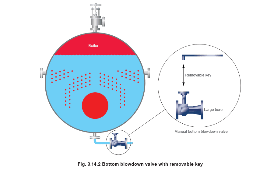
Bottom blowdown valve
Bottom blowdown valve
In the UK, this type of valve is covered in the Factories Act (1961). Section 34 prohibits personnel entering specific boilers unless:
- All inlets through which steam or hot water might enter the boiler (from any other part of the system) are disconnected from that part; or
- All valves or taps controlling entry of steam or water are closed and securely locked. Where there is a common blowdown pipe or vessel, the blowdown valve is constructed so that it can only be opened by a key which cannot be removed until the blowdown valve is closed; and that this is the only key in use in the boiler house.
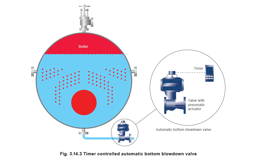
 Timer controlled automatic bottom blowdown
It is now possible to automate the bottom blowdown valve using a proprietary timer linked to a pneumatically operated ball valve.
The timer should be capable of opening the valve at a specific time, and holding it open for a set number of seconds.
The use of automatic bottom blowdown ensures that this important action is carried out regularly and releases the boiler attendant for other duties.
With multi-boiler installations, it is necessary to interlock the valves so that not more than one can be open at any one time, as this would overload the blowdown vessel. This can be done most simply by staggering the setting times of the individual blowdown timers, or by setting the individual blowdown times in sequence.
Timer controlled automatic bottom blowdown
It is now possible to automate the bottom blowdown valve using a proprietary timer linked to a pneumatically operated ball valve.
The timer should be capable of opening the valve at a specific time, and holding it open for a set number of seconds.
The use of automatic bottom blowdown ensures that this important action is carried out regularly and releases the boiler attendant for other duties.
With multi-boiler installations, it is necessary to interlock the valves so that not more than one can be open at any one time, as this would overload the blowdown vessel. This can be done most simply by staggering the setting times of the individual blowdown timers, or by setting the individual blowdown times in sequence.
Blowdown vessels, as required by UK standards
Blowdown vessels, as required by UK standards
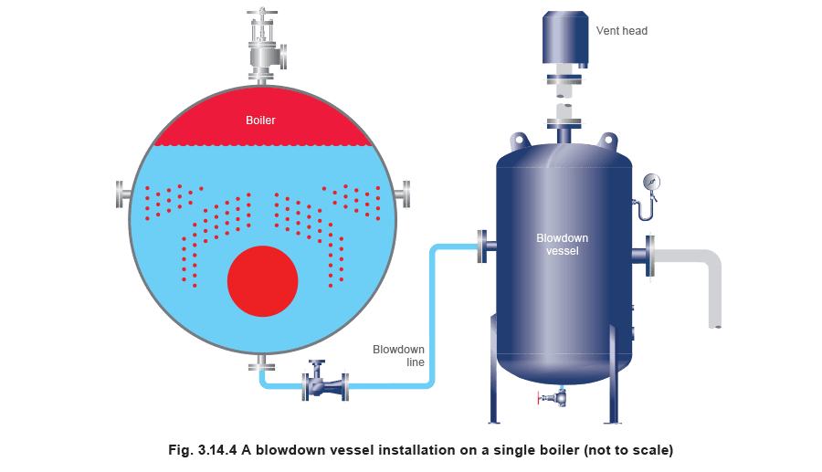
Blowdown vessels are a preferred alternative to blowdown pits. The following information is extracted from HSE Guidance Note PM60 and provides information that may be useful in places other than the UK:
Traditionally, blowdown vessels have had tangential inlets. However, this has meant that the vessels have been structurally weak at the point where the inlet enters.
A preferred alternative is to bring the blowdown line in radially, giving a structurally superior vessel, and then fitting a diffuser inside the vessel. This arrangement also reduces the erosion which could occur inside a vessel with a tangential inlet.
Construction standard
The vessel will need to conform to the European Pressure Equipment Directive (2002) for Group 2 gases. This directive instructs the manufacturer to conform to design and manufacturing standards. As this is a pressure vessel specification, the vessel also needs provision for inspection including an access door and a drain.
Design temperature and pressure
The blowdown vessel design pressure should be at least 25% of the boiler maximum working pressure and the design temperature should be greater than or equal to the saturation temperature for the vessel design pressure.
 Size
This depends on the boiler pressure and blowdown line size, however:
Size
This depends on the boiler pressure and blowdown line size, however:
- The vent should be large enough, that pressure within the vessel does not exceed 0.35 bar g.
- The volume of standing water must ensure that the overflowing water temperature does not exceed 43°C. Operation The vessel should operate with a quantity of standing water, and the water quantity should be at least twice the quantity of blowdown water. Approximately half of the tank’s volume should be occupied by standing water and the remainder as air space. Vent The vent should ensure that flash steam is vented safely and there is no significant carryover of water at the exit to the vent pipe. The vent should be as straight as possible and ideally terminated with a vent head. Tapping for a pressure gauge The vessel must have a tapping for a pressure gauge, as the vessel is manufactured to a pressure vessel specification and regular testing and inspection are required. Cooling system A cooling device should be fitted to the vessel if the hot water temperature causes the outlet temperature at blowdown to exceed the permissible limit. The most cost-effective choice for this application is a self-acting control valve. If the temperature exceeds the set temperature, the valve will open and allow cold mains water into the vessel.
Multi-boiler installations
Multi-boiler installations
The piping arrangement for multi-boiler installations is covered in the UK HSE Guidance Note (PM60); the following points are made:
Operation
Only one boiler can be blown down at any one time. In fact, sizing of the blowdown vessel will be based on the highest pressure boiler with the biggest blowdown line size. Reference is also made to the UK Factories Act (1961) which states the same thing.
Piping
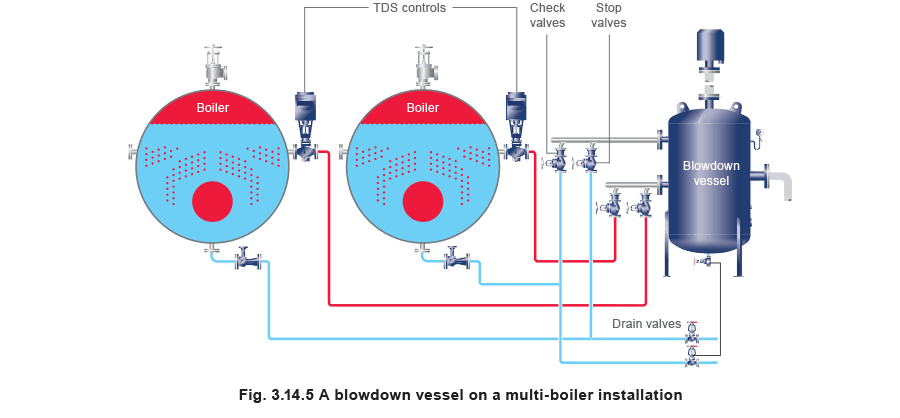
Figure 3.14.5 shows the recommended layout for multiple boiler installations where the bottom and TDS blowdown lines are taken back separately to the blowdown vessel. Manifolding should be at the vessel and not at the boiler. Separate connections are required on the vessel for bottom blowdown and for TDS blowdown return lines.
A third connection is also needed on the vessel to comply with UK Guidance Notes (BG01 and INDG436) regarding water level control in boilers. This requires a connection for the blowdown from control chambers and level gauge glasses.
Valving
Where blowdown lines connect into an inlet manifold on the vessel, each must be fitted with either a screw down non-return valve or, a non-return valve and an isolating valve. This is to prevent the possibility of steam and pressurised hot water being blown from one working boiler into another (inside which personnel may be working) during maintenance.
The preference is for two separate valves. The check valve will have to work regularly, hence wear on the seat is inevitable.