Water-tube Boilers
Description of water tube boilers including operation, types and benefits; also, a brief synopsis on how they are applied to combined heat and power generation.
Water-tube Boilers
Water-tube Boilers
 Water-tube boilers differ from shell type boilers in that the water is circulated inside the tubes, with the heat source surrounding them. Referring back to the equation for hoop stress (Equation 3.2.1), it is easy to see that because the tube diameter is significantly smaller, much higher pressures can be tolerated for the same stress.
Water-tube boilers are used in power station applications that require:
Water-tube boilers differ from shell type boilers in that the water is circulated inside the tubes, with the heat source surrounding them. Referring back to the equation for hoop stress (Equation 3.2.1), it is easy to see that because the tube diameter is significantly smaller, much higher pressures can be tolerated for the same stress.
Water-tube boilers are used in power station applications that require:
- A high steam output (up to 500 kg/s).
- High pressure steam (up to 160 bar).
- Superheated steam (up to 550°C). However, water-tube boilers are also manufactured in sizes to compete with shell boilers. Small water-tube boilers may be manufactured and assembled into a single unit, just like packaged shell boilers, whereas large units are usually manufactured in sections for assembly on site. Many water-tube boilers operate on the principle of natural water circulation (also known as 'thermosiphoning'). This is a subject that is worth covering before looking at the different types of water-tube boilers that are available. Figure 3.3.2 helps to explain this principle:
- Cooler feedwater is introduced into the steam drum behind a baffle where, because the density of the cold water is greater, it descends in the 'downcomer' towards the lower or 'mud' drum, displacing the warmer water up into the front tubes.
- Continued heating creates steam bubbles in the front tubes, which are naturally separated from the hot water in the steam drum, and are taken off.
However, when the pressure in the water-tube boiler is increased, the difference between the densities of the water and saturated steam falls, consequently less circulation occurs. To keep the same level of steam output at higher design pressures, the distance between the lower drum and the steam drum must be increased, or some means of forced circulation must be introduced.
 Water-tube boiler sections
The energy from the heat source may be extracted as either radiant or convection and conduction.
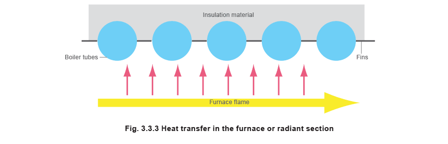
The furnace or radiant section
This is an open area accommodating the flame(s) from the burner(s). If the flames were allowed to come into contact with the boiler tubes, serious erosion and finally tube failure would occur.
The walls of the furnace section are lined with finned tubes called membrane panels, which are designed to absorb the radiant heat from the flame.
Water-tube boiler sections
The energy from the heat source may be extracted as either radiant or convection and conduction.
The furnace or radiant section
This is an open area accommodating the flame(s) from the burner(s). If the flames were allowed to come into contact with the boiler tubes, serious erosion and finally tube failure would occur.
The walls of the furnace section are lined with finned tubes called membrane panels, which are designed to absorb the radiant heat from the flame.
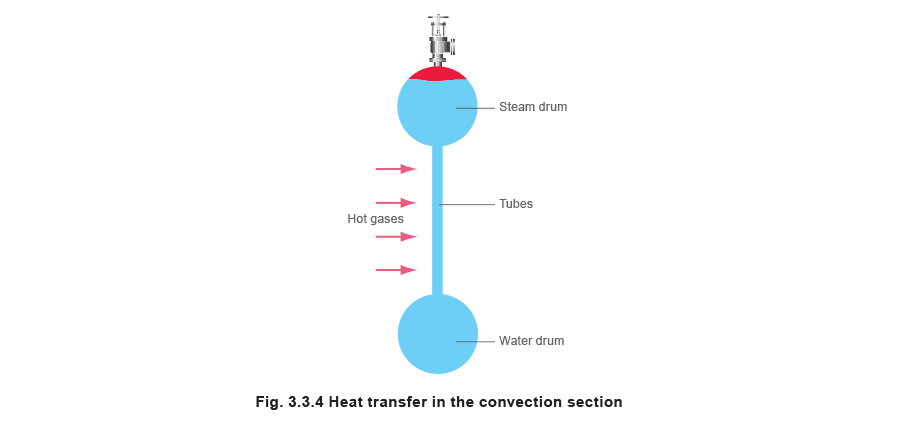
Convection section
Convection section
This part is designed to absorb the heat from the hot gases by conduction and convection.
Large boilers may have several tube banks (also called pendants) in series, in order to gain maximum energy from the hot gases.
 Water-tube boiler designation
Water-tube boilers are usually classified according to certain characteristics, see Table 3.3.1.
Water-tube boiler designation
Water-tube boilers are usually classified according to certain characteristics, see Table 3.3.1.

Alternative water-tube boiler layouts
Alternative water-tube boiler layouts
The following layouts work on the same principles as other water-tube boilers, and are available with capacities from 5 000 kg/h to 180 000 kg/h.
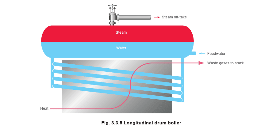
Longitudinal drum boiler
The longitudinal drum boiler was the original type of water-tube boiler that operated on the thermo-siphon principle (see Figure 3.3.5).
Cooler feedwater is fed into a drum, which is placed longitudinally above the heat source. The cooler water falls down a rear circulation header into several inclined heated tubes. As the water temperature increases as it passes up through the inclined tubes, it boils and its density decreases, therefore circulating hot water and steam up the inclined tubes into the front circulation header which feeds back to the drum. In the drum, the steam bubbles separate from the water and the steam can be taken off.
Typical capacities for longitudinal drum boilers range from 2 250 kg/h to 36 000 kg/h.
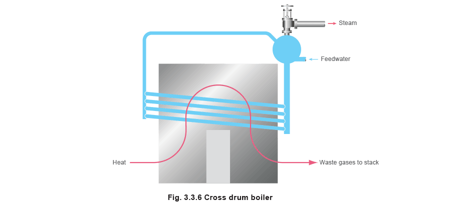
Cross drum boiler
Cross drum boiler
The cross drum boiler is a variant of the longitudinal drum boiler in that the drum is placed cross ways to the heat source as shown in Figure 3.3.6. The cross drum operates on the same principle as the longitudinal drum except that it achieves a more uniform temperature across the drum. However it does risk damage due to faulty circulation at high steam loads; if the upper tubes become dry, they can overheat and eventually fail.
The cross drum boiler also has the added advantage of being able to serve a larger number of inclined tubes due to its cross ways position.
Typical capacities for a cross drum boiler range from 700 kg/h to 240 000 kg/h.
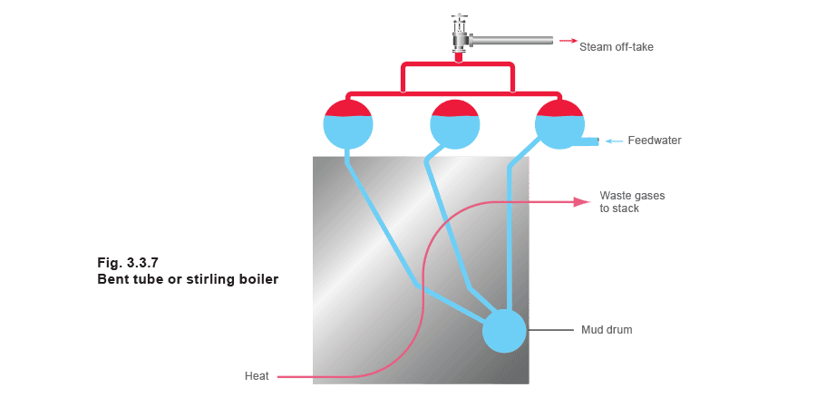
Bent tube or Stirling boiler
Bent tube or Stirling boiler
A further development of the water-tube boiler is the bent tube or Stirling boiler shown inFigure 3.3.7. Again this operates on the principle of the temperature and density of water, but utilises four drums in the following configuration. Cooler feedwater enters the left upper drum, where it falls due to greater density, towards the lower, or water drum. The water within the water drum, and the connecting pipes to the other two upper drums, are heated, and the steam bubbles produced rise into the upper drums where the steam is then taken off.
The bent tube or Stirling boiler allows for a large surface heat transfer area, as well as promoting natural water circulation.
Advantages of water-tube boilers:
- They have a small water content, and therefore respond rapidly to load change and heat input.
- The small diameter tubes and steam drum mean that much higher steam pressures can be tolerated, and up to 160 bar may be used in power stations.
- The design may include many burners in any of the walls, giving horizontal, or vertical firing options, and the facility of control of temperature in various parts of the boiler. This is particularly important if the boiler has an integral superheater, and the temperature of the superheated steam needs to be controlled.
Disadvantages of water-tube boilers:
- They are not as simple to make in the packaged form as shell boilers, which means that more work is required on site.
- The option of multiple burners may give flexibility, but the 30 or more burners used in power stations means that complex control systems are necessary.
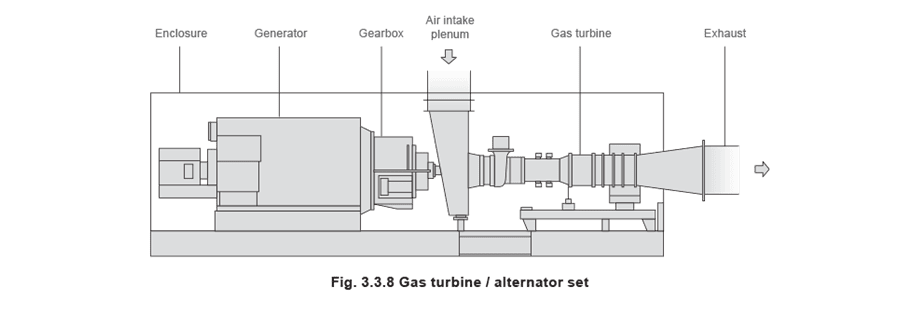
Combined heat and power (CHP) plant
Combined heat and power (CHP) plant
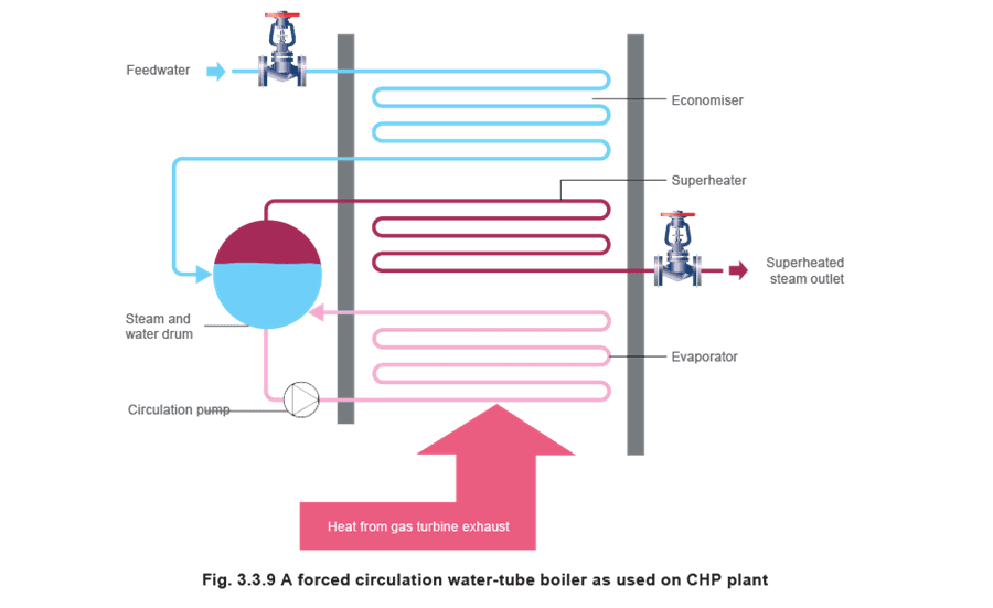
The water-tube boilers described above are usually of a large capacity. However, small, special purpose, smaller waste heat boilers to be used in conjunction with land based gas turbine plants are in increasing demand. Several types of steam generating land based gas turbine plant are used:
- Combined heat and power These systems direct the hot exhaust gases from a gas turbine (approximately 500°C) through a boiler, where saturated steam is generated and used as a plant utility. Typical applications for these systems are on plant or sites where the demands for electricity and steam are in step and of proportions which can be matched to a CHP system.
Efficiencies can reach 90%.
- Combined cycle plant
These are extensions to CHP systems, and the saturated steam is taken through a superheater to produce superheated steam. The superheater may be separately fired because of the comparatively low temperature of the gas turbine exhaust. The superheated steam produced is directed to steam turbines which drive additional alternators, and generate electricity.
The turndown ratio of these plants is poor, because of the need for the turbine to rotate at a speed synchronised to the electrical frequency. This means that it is only practical to run these plants at full-load, providing the base load of steam to the plant.
Because of the relatively low temperature of the gas turbine exhaust, compared to the burner flame in a conventional boiler, a much greater boiler heat transfer area is required for a given heat load. Also, there is no need to provide accommodation for burners. For these reasons, water-tube boilers tend to provide a better and more compact solution. Because efficiency is a major factor with CHP decision-makers, the design of these boilers may well incorporate an economiser (feedwater heater).
If the plant is 'combined cycle' the design may also include a superheater. However, the relatively low temperatures may mean that additional burners are required to bring the steam up to the specification required for the steam turbines.